Types and Applications

| LOOP HEIGHT (mil) | CC-150 | CC-151 | CC-152 | CC-153 | CC-550 |
| 6-8 | 4-6 | 8 OR ABOVE | 4 OR BELOW | 4 OR BELOW | |
| LOOP SPAN (mil) | 200 0R BELOW | 250 0R BELOW | 150 0R BELOW | 300 0R BELOW | 300 0R BELOW |
| HEAT AFFECTED ZONE H.A.Z. (mil) |
5 0R BELOW | 4 0R BELOW | 6 0R BELOW | 3 0R BELOW | 3 0R BELOW |
| REMARKS | THE ABOVE DATA ARE BASED ON 1.0 mil WIRE DIAMETER TEST RESULTS | ||||
| APPLICATIONS | COB, S0T, PLCC, QFP, SOIC, TSOP | BGA, COB, QFP, PLCC, SOT, SOIC, TSOP, TQFP | S0T, SOIC, PLCC, TO, COB, TRANSISTORS REQUIRES LARGER WIRE SIZE | BGA, QFP, MQFP, TSOP, VSSOP, FINE & SUPER FINE PITCH BGA's REQUIRES SUPER FINE WIRE SIZE | BGA, QFP, MQFP, TQFP, VSSOP, SUPER FINE PITCH BGA's REQUIRES SUPER FINE WIRE SIZE, BUMPS FOR FLIP CHIP |
Product Description
CCC Bonding Wire is designed to provide optimum bondability, stability and reliability for a wide range of Metallization, Package geometric configuration and technologies.
CC - 150
Medium strength, all-purpose gold bonding wire, designed for both low lead count discrete devices and the most complex high lead count multi-chip modules as well as chip on board applications. Consistent performance on both manual and high-speed automatic bonding equipments.
CC - 151
High strength, all-purpose gold bonding wire for long and/or low loop applications, designed for the most complex high lead count multi-chip modules. Consistent performance on high-speed automatic bonding equipments.
CC - 152
Soft, all-purpose gold bonding wire for high or flexible loop applications and for larger wire diameter applications, designed for low lead count discrete and power devices. Consistent performance on both manual and high-speed automatic bonding equipments.
CC - 153
Very high strength, fine diameter gold bonding wire for ultra long and/or low loop, fine pitch and very fine wire size applications, designed for most complex high lead count and fine pitch devices. Consistent performance on high-speed automatic bonding equipments.
CC - 550
Super high strength, fine diameter gold-1% Pd bonding wire for ultra long and/or low loop, fine pitch and very fine wire size applications, designed for most complex high lead count and fine pitch devices. Reproducible ball and ball neck properties for consistent bump formation in bumped die applications (e.g. Flip Chip).
Specifications
| Wire Diameter | CC-150 | CC-151 | CC-152 | CC-153 | CC-550 | ||||||
| Mils | Microns | Tensile Strength (gms) |
Elongation (%) |
Tensile Strength (gms) |
Elongation (%) |
Tensile Strength (gms) |
Elongation (%) |
Tensile Strength (gms) |
Elongation (%) |
Tensile Strength (gms) |
Elongation (%) |
| 0.70 | 18 | 3 - 6 | 2 - 5 | 4 - 7 | 2 - 5 | TO BE SPECIFIED |
6 - 9 | 2 - 5 | 7 min. | 2 - 5 | |
| 0.80 | 20 | 4 - 7 | 2 - 5 | 6 - 9 | 2 - 5 | 7 - 10 | 2 - 6 | 8 min. | 2 - 5 | ||
| 0.90 | 23 | 6 - 9 | 3 - 6 | 8 - 11 | 3 - 6 | 10 - 13 | 3 - 6 | 10 min. | 3 - 6 | ||
| 0.95 | 24 | 7 - 10 | 3 - 6 | 9 - 12 | 3 - 6 | 10.5 - 13.5 | 2 - 7 | 11 - 14 | 3 - 6 | ||
| 1.00 | 25 | 8 - 11 | 3 - 6 | 10 - 13 | 3 - 6 | 11 - 15 | 2 - 7 | 12 - 15 | 3 - 6 | ||
| 1.10 | 28 | 10 - 13 | 3 - 6 | 12 - 15 | 3 - 6 | 9 - 13 | 3 - 6 | 13 - 17 | 2 - 7 | 17 - 21 | 0.5 - 3 |
| 1.20 | 30 | 12 - 16 | 3 - 6 | 14 - 18 | 3 - 6 | 11 - 15 | 3 - 6 | TO BE SPECIFIED |
TO BE SPECIFIED |
||
| 1.25 | 32 | 13 - 17 | 3 - 6 | 15 - 19 | 3 - 6 | 12 - 16 | 3 - 6 | ||||
| 1.30 | 33 | 15 - 19 | 3 - 6 | 17 - 21 | 3 - 6 | 14 - 18 | 3 - 6 | ||||
| 1.50 | 38 | 20 - 25 | 3 - 7 | 23 - 28 | 3 - 7 | 18 - 23 | 3 - 7 | ||||
| 2.00 | 50 | 35 - 45 | 4 - 8 | 40 - 50 | 4 - 8 | 30 - 40 | 4 - 8 | ||||
| 3.00 | 75 | 90 - 100 | 4 - 8 | To be specified | 88 - 98 | 4 - 8 | |||||
| *Other requirements can be met per Customer Specification. | |||||||||||
|
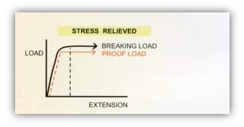
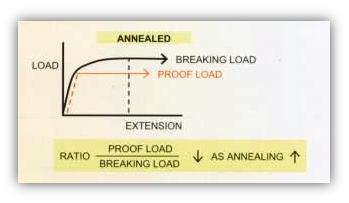
The Effect of Heat Typical tensile test curves are shown for stress-relieved and annealed gold wires. These curves illustrate that the ratio proof load/breaking load is a very sensitive function of the effect of heat on the material and decreases as the material softens. |
|
|
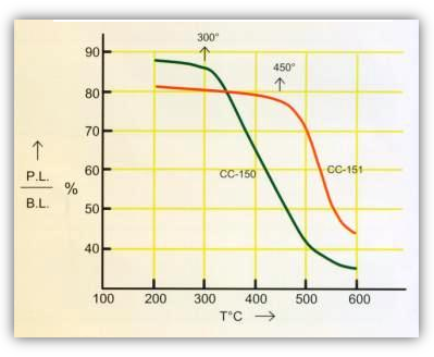
The variation of this ratio, as a function of annealing temperature, for a particular type of gold can therefore provide a clear indication of the effect of heat on that material. The P.L./B.L. % ratio is plotted as a function of temperature for the CC-150 and CC-151 gold wires. The curves show that much more thermal energy is required to soften the CC-151 material. This characteristic provides a short heat-affected zone (H.A.Z.) in the bond neck above the ball for the CC-151 material which facilitates low loop formation.
|
|
Wire Footage and Spool Size
| WIRE DIAMETER | STANDARD FOOTAGE/SPOOL | |||||||
| 1/2 INCH SPOOL | 2x1 INCH SPOOL | 2x2 INCH SPOOL | ||||||
|
500 ft. MAX OR (150 me.) |
1,640 ft. OR (500 me.) |
1,640 ft. OR (500 me.) |
|||||
|
500 ft. MAX OR (150 me.) |
1,640 ft. up to 3,280 ft. OR (500 me. up to 1,000 me.) |
3,280 ft. up to 9,840 ft. OR (1,000 me. up to 3,000 me.) |
|||||
|
210 ft. MAX |
1,640 ft. up to 3,280 ft. OR (500 me. up to 1,000 me.) |
3,280 ft. up to 9,840 ft. OR (1,000 me. up to 3,000 me.) |
|||||
|
200 ft. MAX |
1,000 ft. up to 3,280 ft. OR (300 me. up to 1,000 me.) |
3,280 ft. up to 6,560 ft. OR (1,000 me. up to 2,000 me.) |
|||||
|
90 ft. MAX | 375 ft. MAX | 750 ft. MAX | |||||
| *Other footages can be supplied per Customer Specification. | ||||||||
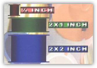
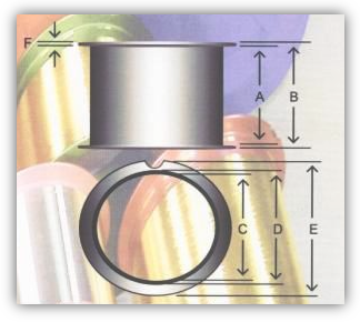
| SIZE | COLOR | A (mm) | B (mm) | C (mm) | D (mm) | E (mm) | F (mm) |
| 1/2" | Red | 18.0 | 19.0 | 12.7 | 13.5 | 17.4 | 0.40 |
| 2" X 1" | Green | 26.5 | 28.0 | 48.85 | 50.31 | 58.5 | 0.75 |
| 2" X 1" | Blue | 26.5 | 28.0 | 48.85 | 50.31 | 58.5 | 0.75 |
| 2" X 1" | Black | 26.5 | 28.0 | 48.85 | 50.31 | 58.5 | 0.75 |
| 2" X 1" | Yellow | 26.5 | 28.0 | 48.85 | 50.31 | 58.5 | 0.75 |
| 2" X 1" | Light Purple | 26.5 | 28.0 | 48.85 | 50.31 | 58.5 | 0.75 |
| 2" X 1" | Dark Purple | 26.5 | 28.0 | 48.85 | 50.31 | 58.5 | 0.75 |
| 2" X 1" | Red | 26.5 | 28.0 | 48.85 | 50.31 | 58.5 | 0.75 |
| 2" X 1" | Brown | 26.5 | 28.0 | 48.85 | 50.31 | 58.5 | 0.75 |
| 2" X 1" | Gray | 26.5 | 28.0 | 48.85 | 50.31 | 58.5 | 0.75 |
| 2" X 2" | Green | 45.5 | 47.0 | 48.85 | 50.31 | 58.5 | 0.75 |
| 2" X 2" | Blue | 45.5 | 47.0 | 48.85 | 50.31 | 58.5 | 0.75 |
| 2" X 2" | Light Purple | 45.5 | 47.0 | 48.85 | 50.31 | 58.5 | 0.75 |
| 2" X 2" | Dark Purple | 45.5 | 47.0 | 48.85 | 50.31 | 58.5 | 0.75 |
| 2" X 2" | Black | 45.5 | 47.0 | 48.85 | 50.31 | 58.5 | 0.75 |
| 2" X 2" | Silver | 45.5 | 47.0 | 48.85 | 50.31 | 58.5 | 0.75 |
| 80 mm | Black | 49.5 | 50.5 | 77.7 | 80.0 | 85.0 | 1.00 |
| *Other spool color can be supplied per Customer Specification. | |||||||
H.A.Z. and Grain Structure
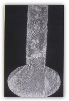
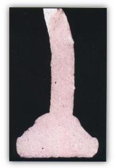
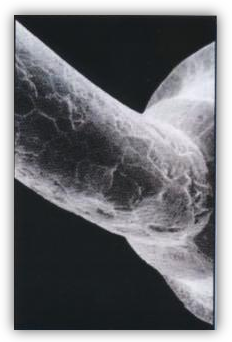
Heat-Affected Zone (H.A.Z.) and Neck Grain Structure
The S.E.M. micrographs show the H.A.Z. and the neck grain structure of the bonding wire. Note the uniformly fine, equiaxed grain structure.
|
Dopants The purity of fine gold bonding wires is typically specified as 99.99 wt% Au. The mechanical properties and thermal characteristics of a particular gold wire are controlled by the addition of dopants at the p.p.m. level. A list of typical dopants is shown and are classified into three types, as a function of the nature of their miscibility with gold in the solid state. |
| |||||||||||||||||||||||||||||||
| Dopant | Au-Rich | Dopant-Rich | ||||||
| Beryllium | Be | - | BeAu3 | BeAu2 | Be3Au4 | BeAu | - | - |
| Calcium | Ca | CaAu4 | CaAu3 | CaAu2 | - | - | Ca4Au3 | Ca2Au |
| Lanthanum | La | - | LaAu3 | LaAu2 | - | LaAu | - | La2Au |
| Cerium | Ce | - | CeAu3 | CeAu2 | - | CeAu | - | Ce2Au |
Thermal Characterization
|
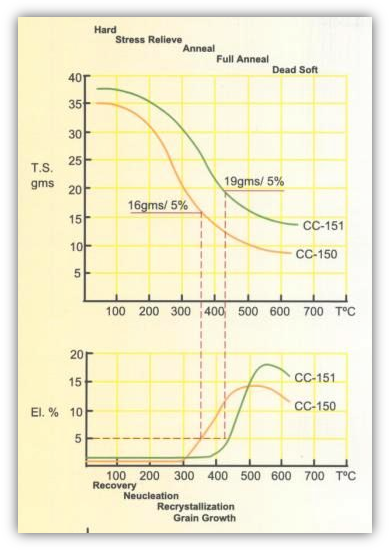
1-3 Mil Au Wires The strength (T.S.) and ductility (EL.) of CC-150 and CC-151 gold wires are shown as a function of temperature. In relation to gold ball bonding, significant features are the high strength of the CC-151 gold in the annealed condition (for long loop) and the relatively high strength and very high ductility of both materials in the dead-soft condition (optimum bond-neck properties). |
|
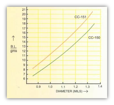
| Tensile Strength vs Diameter Annealed Au Wires |
 |
Featured Products


Home |
Product |
Capabilities |
Certifications |
Information Request |
Contact Us
C.C.C. Bonding Wire Copyright © 2009 All rights reserved.
C.C.C. Bonding Wire Copyright © 2009 All rights reserved.


